INSTALLATION INSTRUCTIONS
1994-97 Dodge Ram 1500/2500
TOOLS RECOMMENDED:
TO ST ART :
9/16 deep socket
ratchet
10mm wrench
15mm deep socket
prybar
rubber mallet
spray lubricant or penetrating oil
anti-seize
reciprocating saw or hack saw
pair of channel lock pliers
2. Disconnect negative battery cable and
allow vehicle exhaust to cool.
3. With vehicle raised and properly sup-
ported, using a reciprocating saw or hack
saw, cut tail pipe approximately 1î behind
rear muffler clamp and in front of tail pipe
hanger.
4. Spray lubricant on lower holes of front
and rear tail pipe hanger rubber grommets.
5. Remove lower bolt from rear tailpipe
hanger.
10. Using some form of heat and force,
disengage and remove muffler without
damaging head pipe.
17. Position 3" clamp (H) over slip joint on
turn out (D) and hand tighten. NOTE: use
anti-seize on threads.
1. Remove and inventory new JBA
exhaust.
11. Align notch with locating pin and install
head pipe (A) using the 2-1/2" clamp (E).
Tighten completely with 9/16" deep wall
socket. NOTE: Use anti-seize on threads.
6. Using a pair of channel lock pliers,
remove front tail pipe hanger rod from
bottom hole in rubber grommet.
7. Remove tail pipe from rear of vehicle.
13. Using the 3" clamp (F), tighten clamp
completely using 9/16" deep wall socket.
NOTE: use anti-seize on threads.
18. Check all pipes for proper clearance
and tighten the 3" clamp (G) completely at
rear of muffler.
19. Check turn out (D) position and tighten
clamp (H) completely.
20. After installation, it is recommended
that all clamps be retightened and joints
tach welded in 3 spots.
21. Using a soft cloth, remove all prints
from turnout tip.
22. Lower vehicle and reattach the nega-
tive battery cable.
NOTES:
1) It may be necessary to loosen and
realign the spare tire for proper clearance.
2) All exhaust systems will expand about 1"
rearward when exhaust temperature start
to rise.
3) Use Anti-seize on threads of clamps.
14. Install 3" clamp (G) over rear slip on
muffler and install tail pipe (C) from rear
of vehicle, bracket end first then slip into
muffler
15. Install front two hangers on tail pipe
(C) into lower holes of rubber grommet.
16. Install 3" clamp (H) over rear of tail
pipe (C). Slip turn out (D) over tail pipe
(C). Slip hanger rod into lower hole in
rubber grommet.
8. Spray penetrating oil on threads of front
muffler clamp.
9. Using a 15mm socket, remove front
muffler clamp.
12. With JBA logo facing rear of vehicle,
install muffler (B) over head pipe (A) mak-
ing sure muffler bottoms out on slip joint.
12. With JBA logo facing rear of vehicle,
install muffler (B) over head pipe (A) mak-
ing sure muffler bottoms out on slip joint.
12. With JBA logo facing rear of vehicle,
install muffler (B) over head pipe (A) mak-
ing sure muffler bottoms out on slip joint.
12. With JBA logo facing rear of vehicle,
install muffler (B) over head pipe (A) mak-
ing sure muffler bottoms out on slip joint.
We recommend taking the truck to a muffler shop and having all slip connections tack welded.
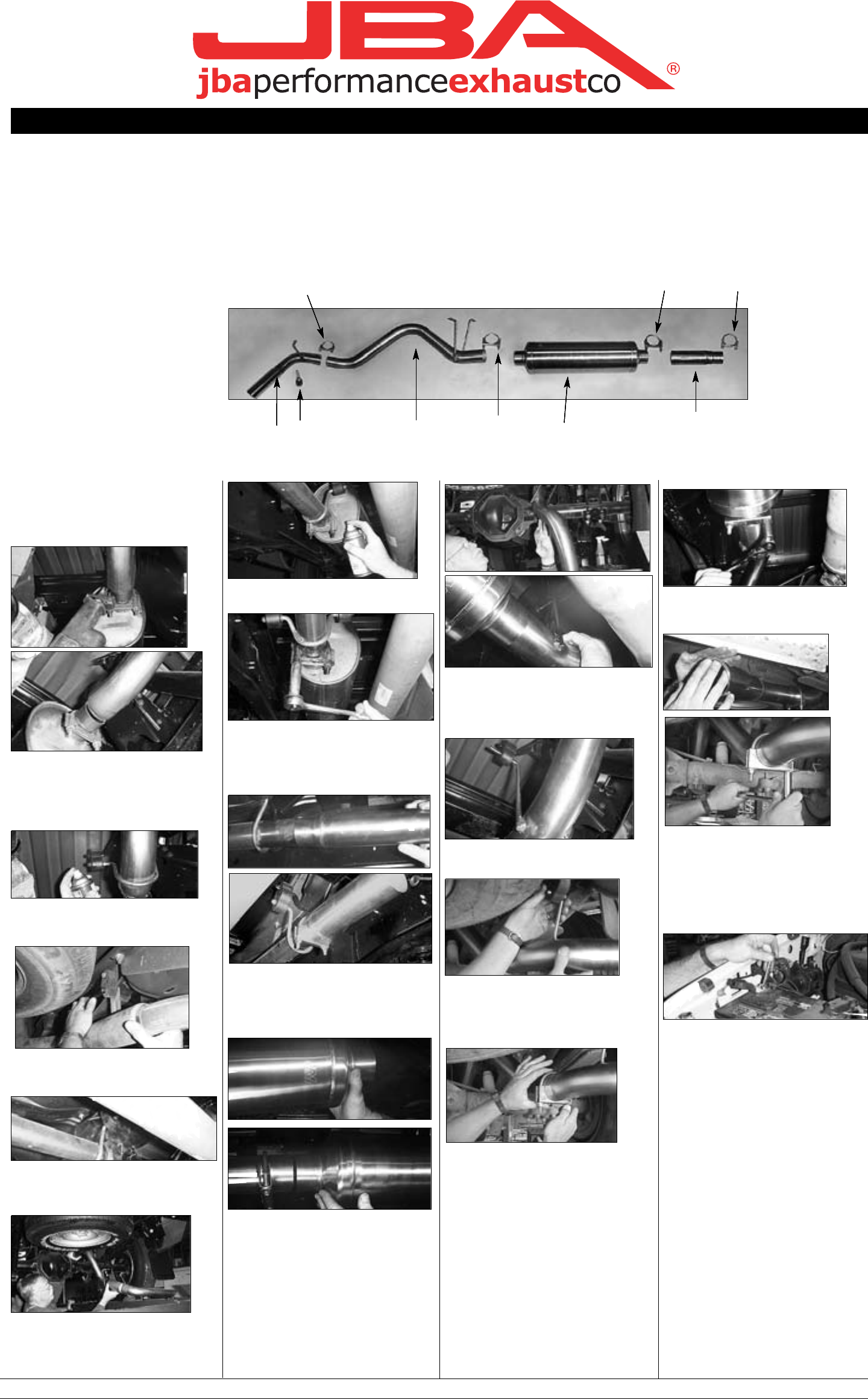
Part s List
A. Head pipe 1
B. Muffler, 24" 1
C. Tail pipe 1
D. Turn out 1
E. 2-1/2" clamp 1
F. 3" clamp 1
G. 3" clamp 1
H. 3" clamp 1
*I. Rear turnout hanger assembly 1
**Installation recommendation:
JBA recommends in most cases that the vehicle be taken to a reputable exhaust shop.
17038
6-21-02
We recommend taking the truck to a muffler shop and having all slip connections tack welded.
Part s List
A. Head pipe 1
B. Muffler, 24" 1
C. Tail pipe 1
D. Turn out 1
E. 2-1/2" clamp 1
F. 3" clamp 1
G. 3" clamp 1
H. 3" clamp 1
*I. Rear turnout hanger assembly 1
**Installation recommendation:
JBA recommends in most cases that the vehicle be taken to a reputable exhaust shop.
17038
6-21-02
H
D
I
B
G
F
E
A
C
* On some model years, it may be necessary to bolt rear
hanger assembly (I) to hole in frame rail to mount turn out (D).
H
D
I
B
G
F
E
A
C
* On some model years, it may be necessary to bolt rear
hanger assembly (I) to hole in frame rail to mount turn out (D).
H
D
I
B
G
F
E
A
C
* On some model years, it may be necessary to bolt rear
hanger assembly (I) to hole in frame rail to mount turn out (D).
H
D
I
B
G
F
E
A
C
* On some model years, it may be necessary to bolt rear
hanger assembly (I) to hole in frame rail to mount turn out (D).
 (4 pages)
 Manymanuals.com
 Manymanuals.de
 Manymanuals.fr
 Manymanuals.it
 Manymanuals.pl
 Manymanuals.cz
 Manymanuals.es
 Manymanuals-pt.com
Commentaires sur ces manuels